
- Home
-
About Us
About Us
No Job Is Too Big or Too Small
-
Our services
Our services
Delivering Superior Performance and Operational Efficacy

-
Methods
Methods
Offering Tailored Solutions For Customer Requirements
Seismic Methods Electrical Methods EM Methods Magnetic Methods GPR Method Gravity Methods Borehole Logging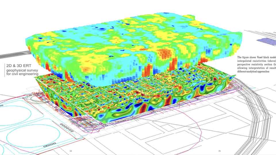
-
Project Cases
-
News
- Contact


Electrical Methods
The electrical properties of the subsurface vary with the ground material, the presence and saturation level of fluids, and the presence of buried objects. Electrical techniques seek to describe the distribution of these properties as a function of depth and horizontal distance.
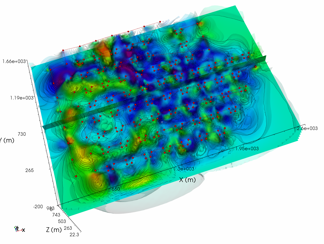
1- 2D & 3D Electrical Resistivity Tomography
2- 1D Vertical Resistivity Tomography
3- Induced Polarization
4- Cross-Hole Resistivity Tomography
Applications
- Ground water and mineral exploration
- Locating Cavities, voids, Tunnels and solution features
- Geological and Stratigraphic mapping
- Determination of depth to bedrock
- Buried foundation mapping
- Mapping and monitoring of groundwater pollution
- Landfill waste mass Investigation
Techniques
-
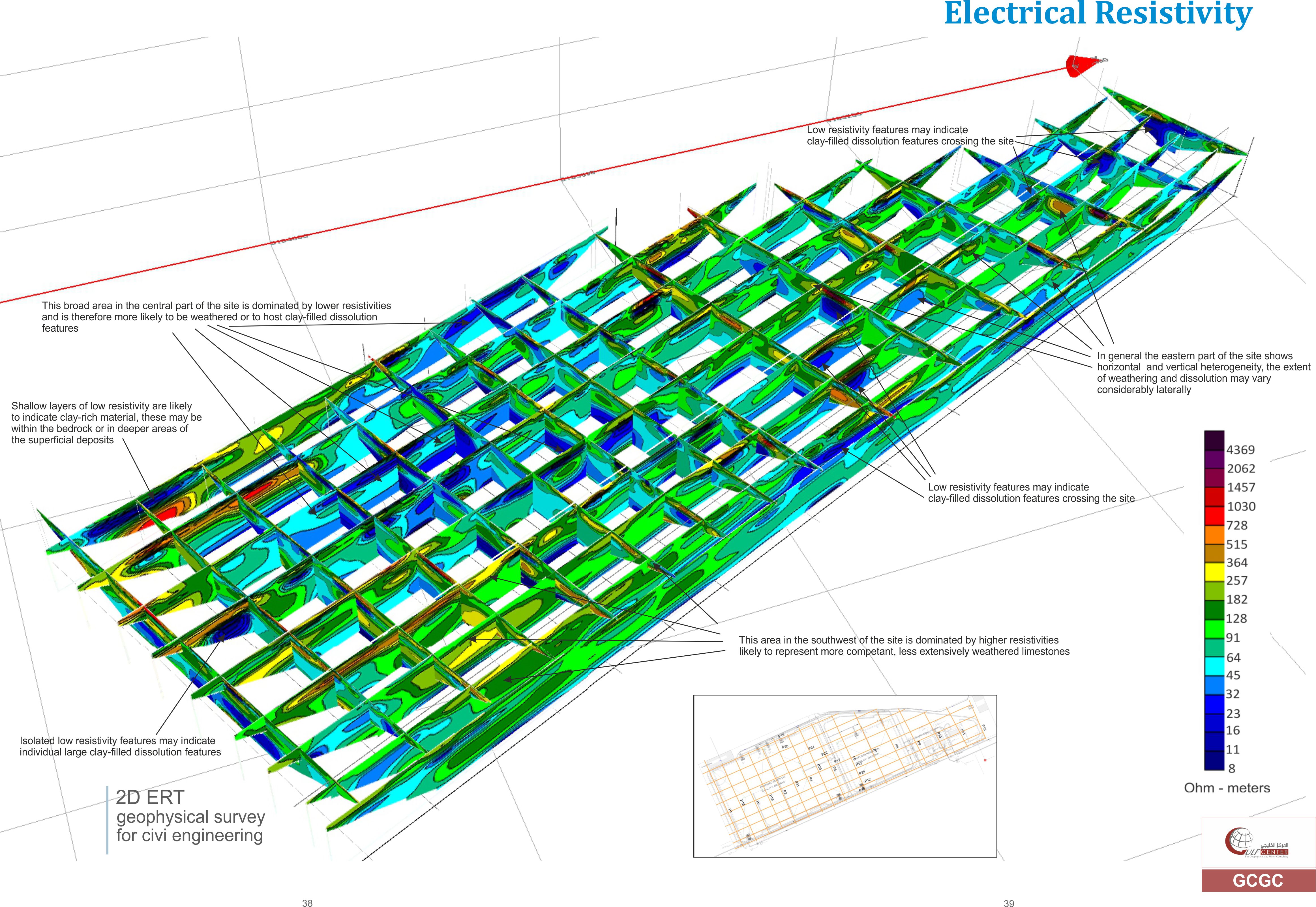
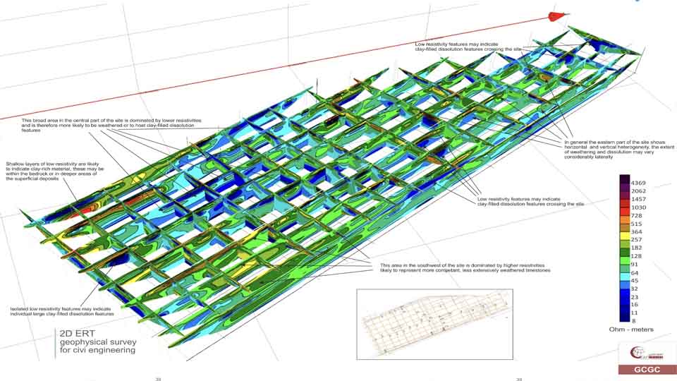
2D & 3D Electrical Resistivity Tomography
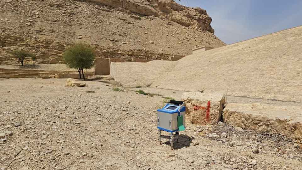
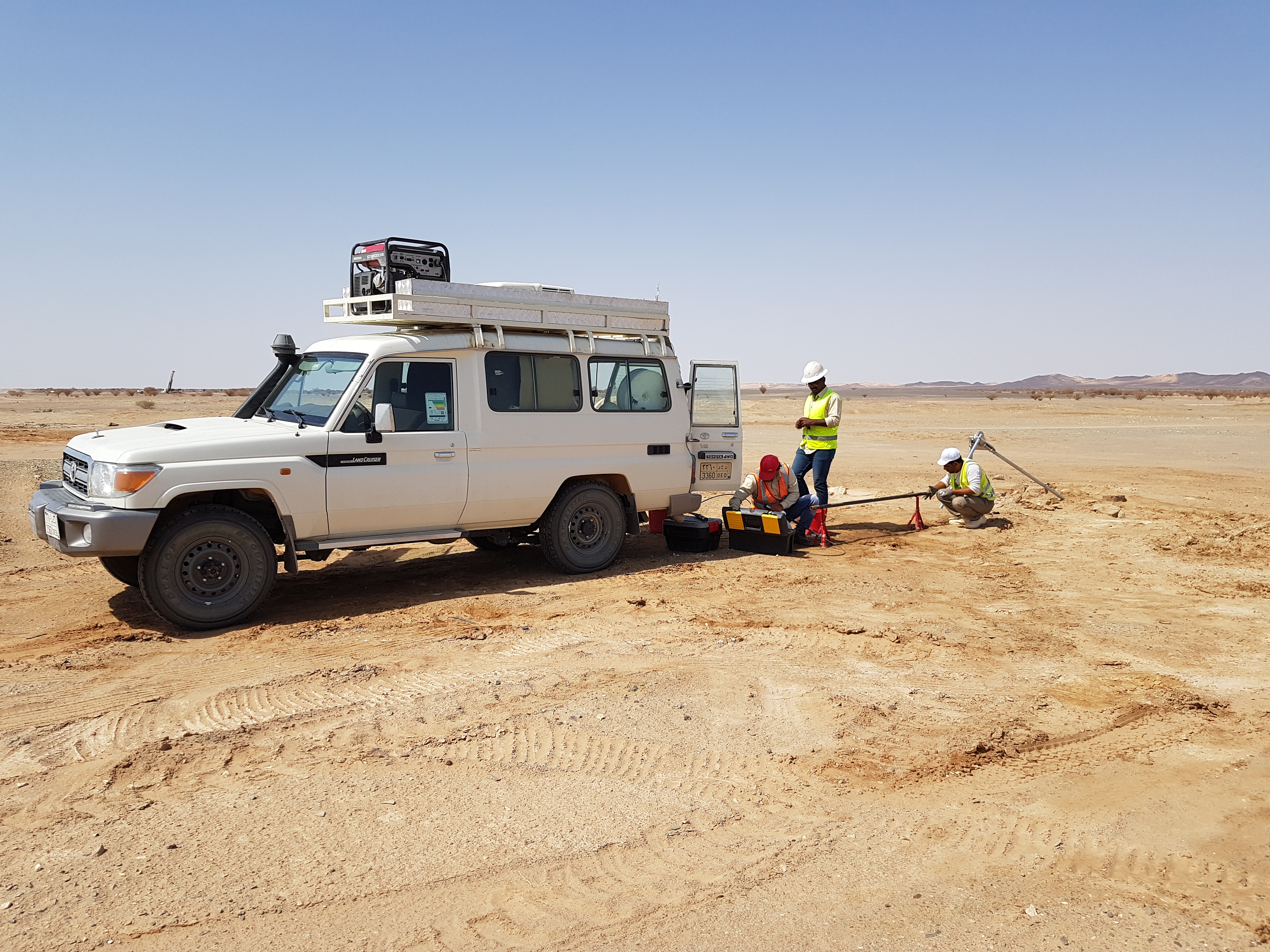
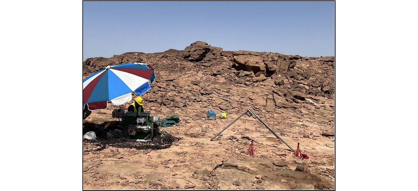
ERT is a geophysical method that uses direct current to measure the earth's resistivity. The current is injected into the subsurface through steel electrodes installed into the ground and the apparent resistivity distribution along a profile or area is measured. -
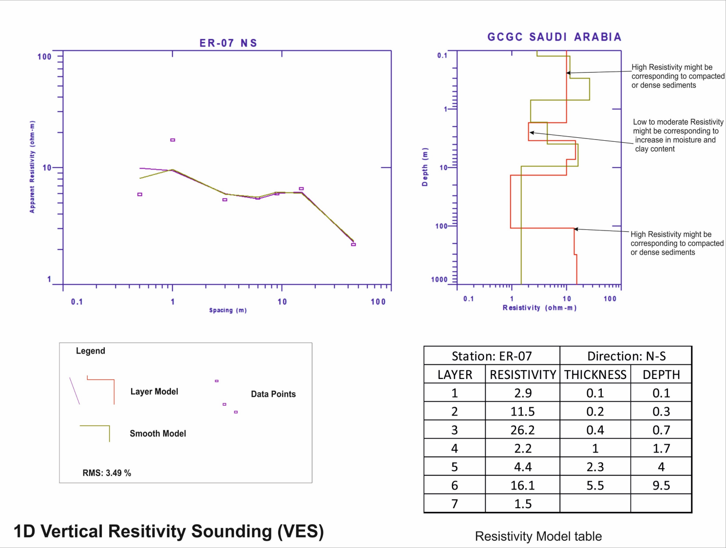
1D Vertical Resistivity Sounding (VES)
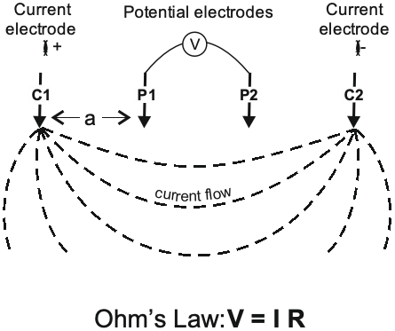
VES is a electrical resistivity method usually conducted using one of two electrode arrays: Schlumberger or Wenner arrays. These are generally 4-electrodes resistivity survey set-ups with progressively larger spacings between electrodes. -
Induced Polarization (IP)
IP is equivalent to a charge / discharge behavior of capacitors when currents are switched on and off. When IP effects are present, a decay curve is observed at the receiving electrodes when the pulse of current is switched off. The chargeability is a measurement of this decay. -
Cross-Hole Resistivity Tomography
Crosshole Resistivity Tomography is the capability to do cross-hole surveys. This are run using a standard surface system but with the addition of specialist downhole cables. The usual depth limits are between 150 to 300m for most applications.